How to mod an MXR Blue Box to increase volume and enhance the sound
The following photo tutorial will show you how to remove a capacitor from your Blue Box to increase the volume and enhance the sound. I will also include instructions on how to add a switch if you chose to want the option of switching between the filtered and nonfiltered sound. First let me list some items that you will need to do this project.
Items Needed for this tutorial, note items marked with an * are only needed for the "Remove the Capacitor ONLY mod."
- Wire cutters *
- Phillips head screwdriver *
- Jeweler's flat head screwdriver *
- Soldering Iron
- Solder
- 1 subminiature switch
- 12 inches of thin wire
- Drill
- 1 drill bit with the correct size for the switch
- First thing you need to do is take your MXR Blue Box apart. This requires the removal of the knobs, use the flat head screwdriver to take the knobs off. Then take the lugs off the pots. The nut for the stompswitch and lastly the two nuts for the input and output jacks.
- Now gently push the stomp switch, while wiggling the board left and right while pulling it out. You may notice that the power adapter may impede your chance of removing it easily. Just push a little harder to one side until it clears the enclosure.
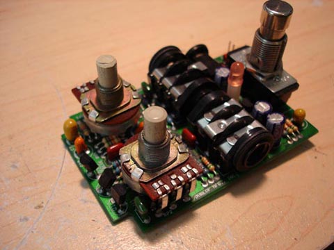
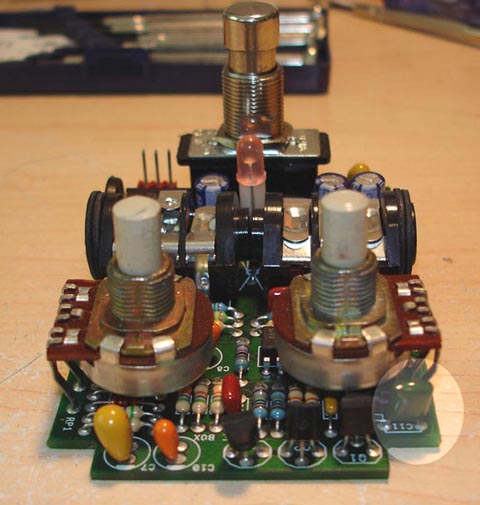
- Now that the board is clear, your board will look like this:
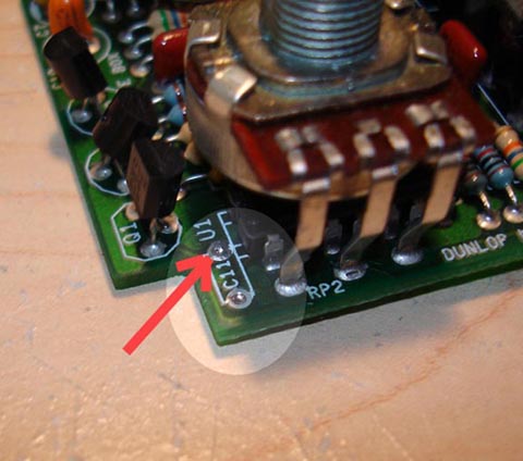
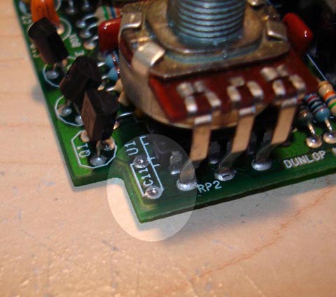
- Now you want to focus on just one capacitor on this board. Do you see
the text C11(appears upside down) on the board? That's the culprit. I highlighted
it for better reference. All you need to do for the "Remove the Capacitor
ONLY mod is take your wire cutters, cut both ends of the capacitor off from
the board, right below where the green is. Put the board back in, going
in reverse what you did before when taking it apart and you are done. If
you want to add a switch like I did, read on.
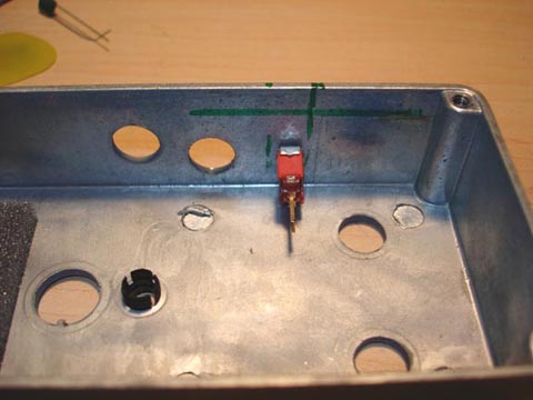
- First you need to take your switch and see if it's possible for it to
fit with all the other existing stuff on the board. What I did was put the
board back into the enclosure and mark where the board was located. In this
photo you will see the green lines, the horizontal line is the circuit board.
Next thing I did was estimate the clearance I was able to play with in mounting
the switch. That is what the two vertical lines are. With the drill press,
I drilled the hole and fitted the switch.
- Now that you have the switch in, I went ahead and cut the 12 inches of wire into two pieces both of equal length. Stripped one end on each wire and soldered those to the switch. I used what is called a Single Pole Double Throw switch (SPDT for short). I soldered the wires to the center lug and one of the other lugs. You leave the other lug ALONE. I suggest cutting it off actually to prevent any contact with the circuit board.
- After the two wires are soldered onto the board, I discarded the old capacitor and replaced it with a smaller value because I liked the filter sound but I wasn't fond of the major volume drop. The original capacitor was a 0.01uF capacitor. I replaced it with a 0.0022uF. You may chose to use the original, that's perfectly fine.
- First you want to solder one of the wires to one of the legs of that capacitor. The other wire, solder that to the circuit board. The trick I did was strip the wire, place a little bit of solder onto the exposed part of the wire so it will be sturdy.
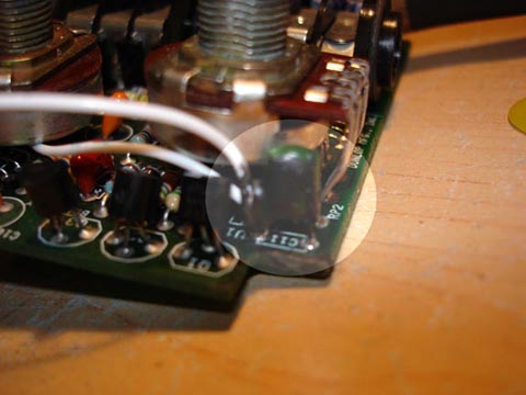
- I took my soldering iron and placed the tip right on the hole along with
the wire and when the solder from both the hole and the wire heated up,
I forced the wire down the hole. Here is the hole I focused on, it's the
one with the arrow pointing to it:
- Next I took the capacitor, with it's one leg left (remember the other
one is soldered to the capacitor) and did the same method, this time with
the OTHER hole that is part of the C11 marking. The other hole is opposite
of the other.
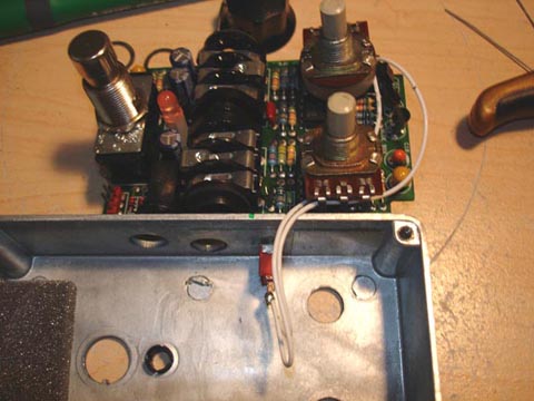
- Plug up the MXR, see how it sounds, then flick the switch, you will notice
a difference in the sound. Cool huh? The end result looks like this? Note,
I painted the capacitor's open leg with liquid rubber to prevent any short
circuits. You could use tape, a peice of paper, whatever. Now remember,
those two white wires are NOT connected to each other!
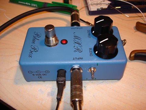
- Here is a picture of the finished item, notice how I routed the wires. There is zero clearance between the board and the walls of the enclosure so it's best to do it this way yet give you some slack so you can pull the board out and do further mods if you like.
- Voila, it's done!
Shawn Royal - Sirkut
Electronics
2005.05.07